Compak K6 Grinder Doserless Conversion - June 2020
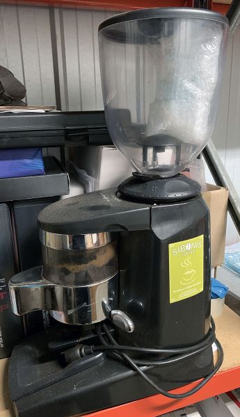

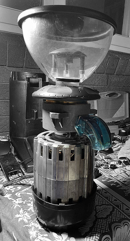
Firstly, a huge thank you goes out to Dean and Rose Kiner, Owners of Siboni's Coffee in Pymble NSW for their kind and generous donation of the Compak K6 Grinder, for Dean's invaluable input throughout the build and inspiration to have made this project possible.
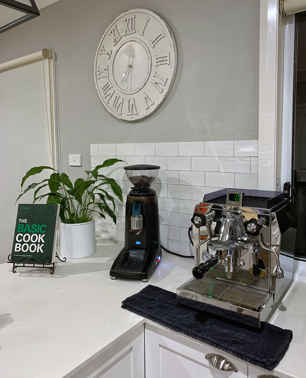
The following words details my recent project journey of converting a Compak K6 Dose Grinder to doserless / grind on demand with a custom designed, programmed and built timer module.
The Compak K6 Grinder was donated in 2019 with the prospect of a project to restore the former Siboni's Coffee shop grinder to a functional doserless grinder.
This grinder will find its new home in Newcastle where its being donated to my sister and Brother-in-law together with my old ECM Giotto to replace their Nescafe capsule machine.
Work commenced on the project on 2 January 2020 beginning with the complete dismantling of the grinder and cleaning of all components.
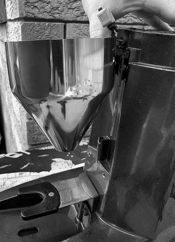
The conversion to doserless would require the removal of the old dose chamber and considerable thoughts and re-engineering the grinder outlet port and mounting a spout or cone.
In keeping with simplicity, a Rancilio Rocky Grinder Doserless spout (which Dean also provided) was the first choice, however other thoughts considered included retrofitting a dose cone from a Mazzer Mini, however, these are rather expensive (over AU$250) and later in the project timeline would prove to have been too tall, pushing the placement of the portafilter holder much lower where the display is positioned.
The next task, reducing the size of the hopper. This accomplished by marking and hand-cutting the hopper and finished off through hand sanding. A felt strip was used on the inside edge of the hopper lid to make for a very nice and snug fit.
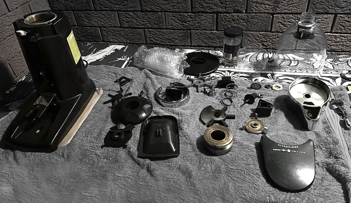

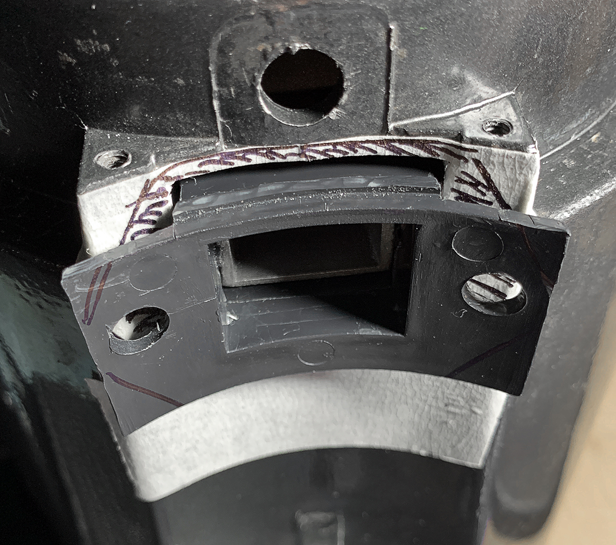
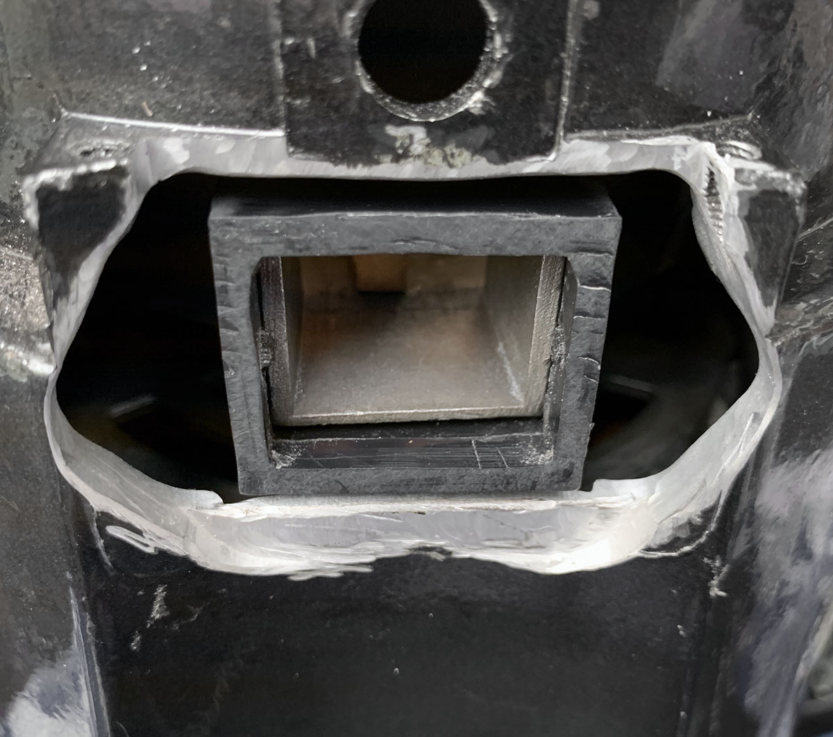
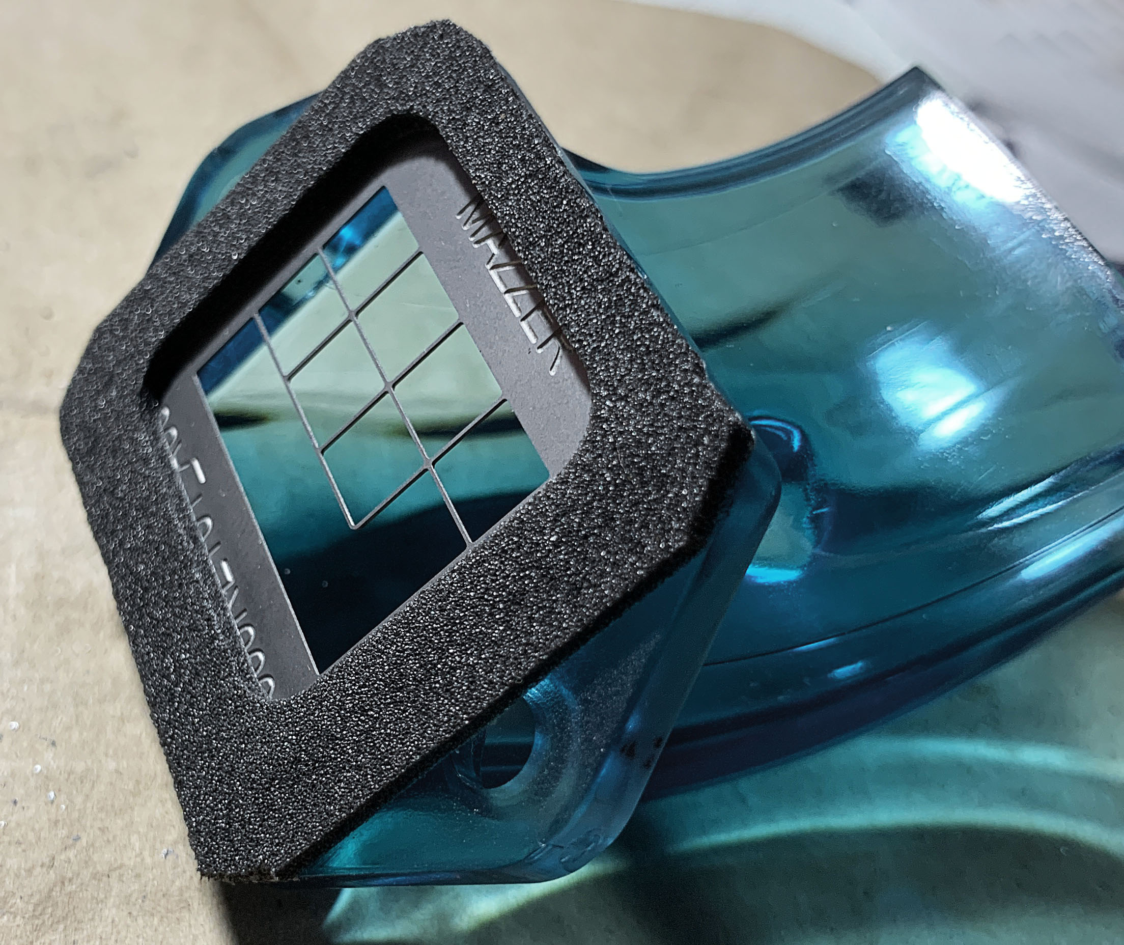

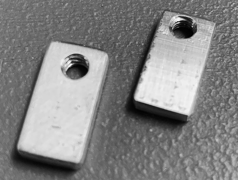
One of a number of engineering challenges was how to engineer and modify the existing housing (which had a curved section where the outlet port is) to mount the Spout (which is a flat mating flange) and mate the spout with the grinder port - this would require modification to both the housing and the original plastic coffee outlet adapter.
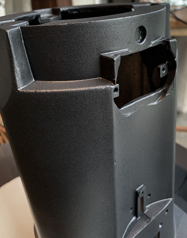
The housing was marked out and a Dremel tool used to 'carve' out the metalwork. The original outlet adapter was modified by cutting off the curved front. The adaptor would then sit flush with the front of the housing.
With the onset of COVID-19 lockdowns, the next three months would put the main grinder project on engineering bench (to decide on how many holes would need to be cut and further, what display to use). The lockdowns would prove useful as this allowed for a second concurrent project which focused on the development and programming of the timer module that would eventually be installed in the grinder.
The design brief for the timer; Functional, simplicity and ease of use with a nice clear display.
Additional features include screen saver mode (screen is turned off after 5 min), and visual LED fades.
The timer module is designed and programmed around the Arduino platform (ATmega328) and finally ported to the "ProMini" board.

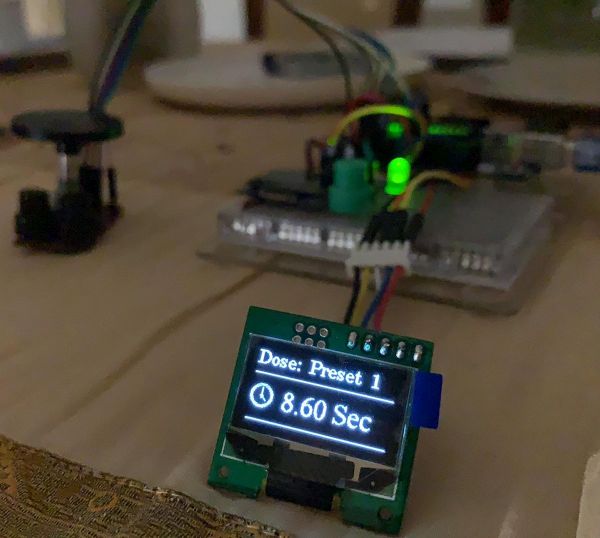

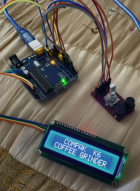
The additional challenge during development, with considerations to the limited physical space to be able to mount the electronics, was what display to use, its physical location and the size of the display.
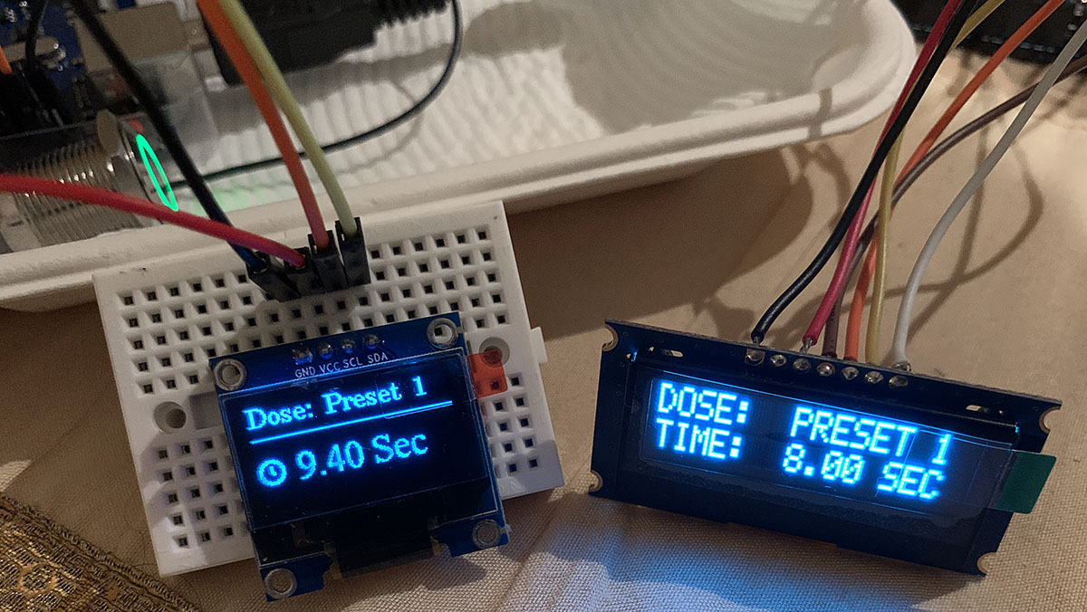
In the early stages of the project, a standard 16x2 character LCD was the original display. A Smaller 16x2 OLED was also tested, however as the project evolved, consideration had to be made that space was limited, and that the larger screens would be difficult to fit.
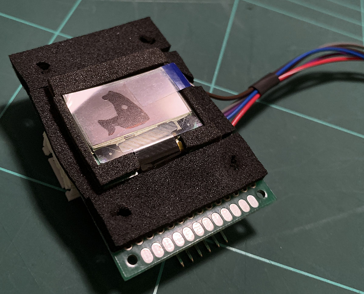
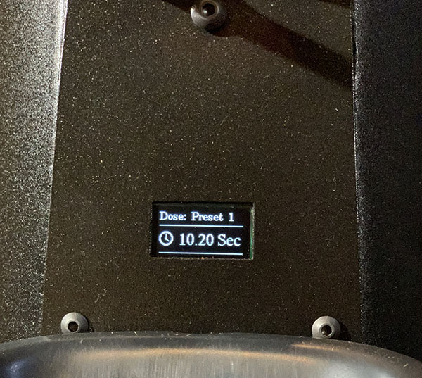
The goal shifted away from text based 16x2 line display with focus to develop the programming for a tiny 128x64 pixel graphical OLED (24mm diagonal) screen with white pixels. The bonus of being a graphical display, allowed for some nice graphic additions as well as a much nicer looking Display.
Another advantage of OLED Displays, is their excellent contrast and clear text.
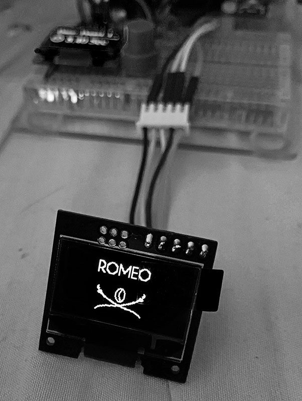
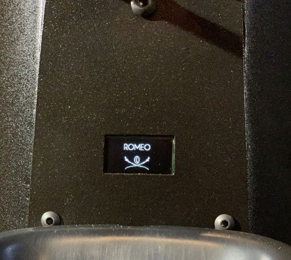
To pay homage to Siboni's Coffee and one of my favourite blends, "Romeo" I programmed the "Romeo" graphic that appears on power-up (can also be user enabled / disabled).
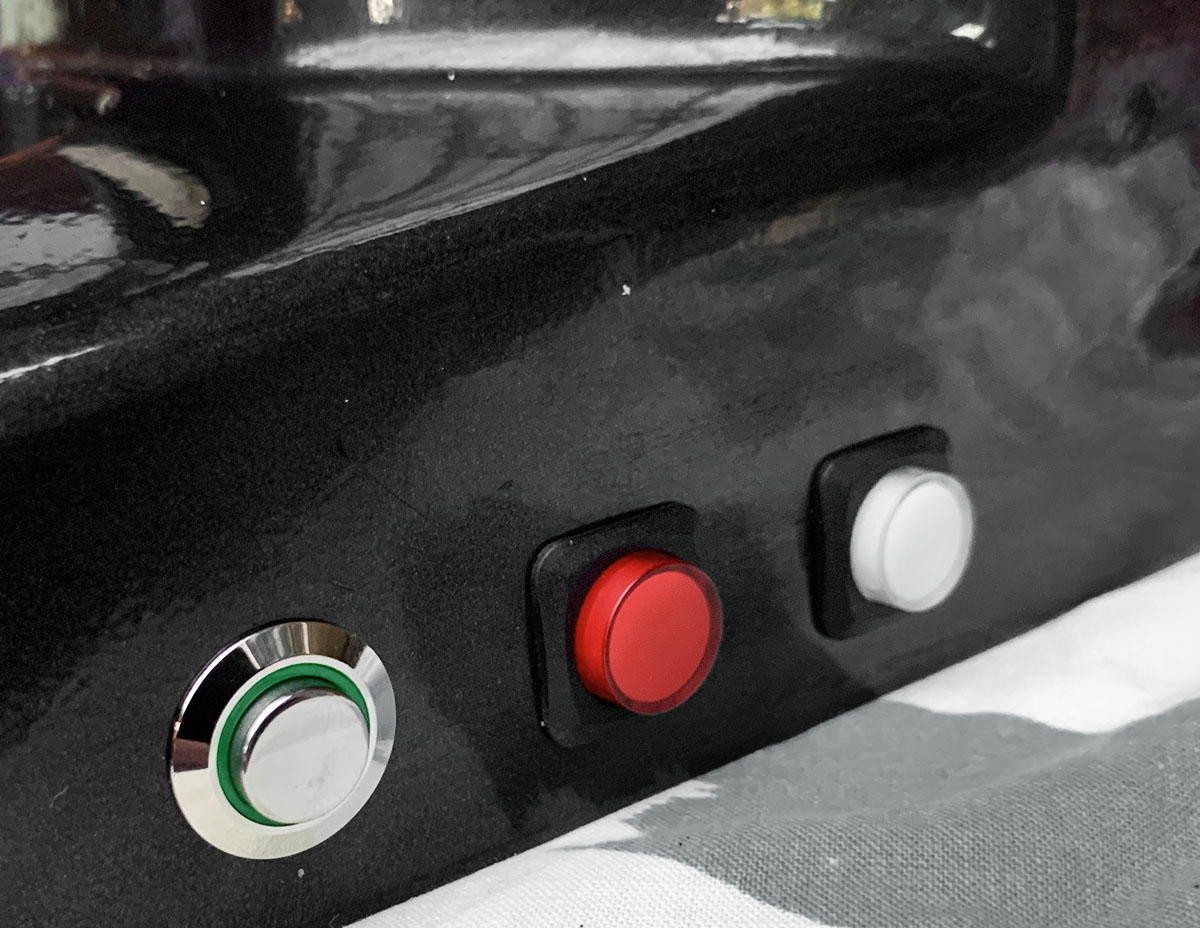
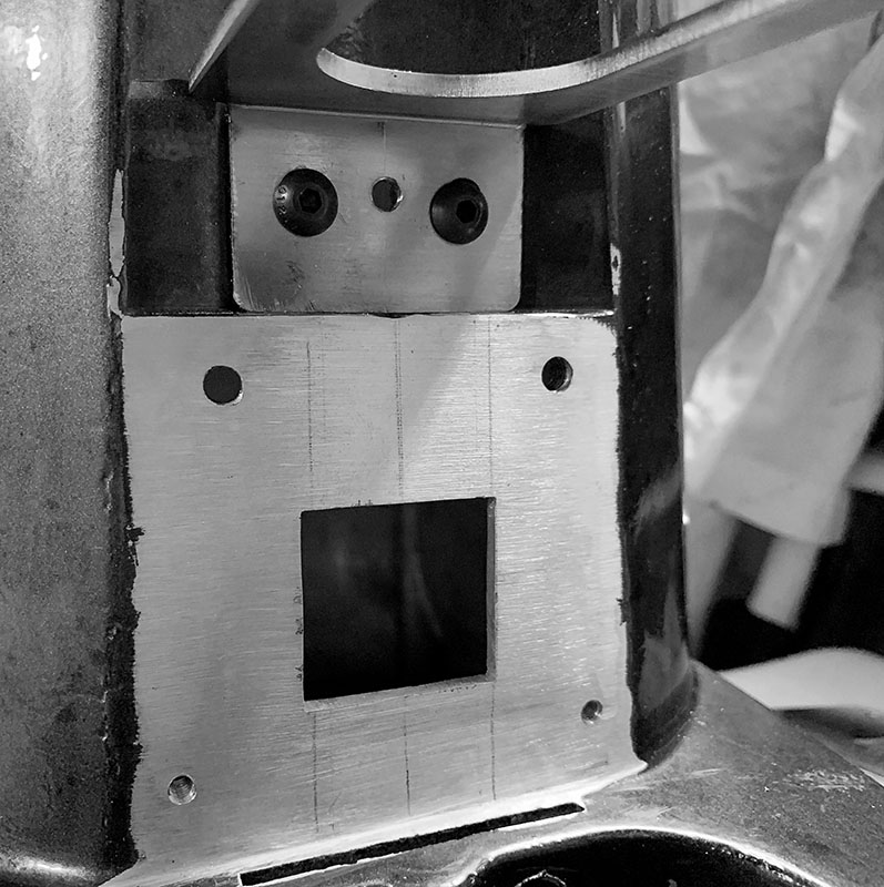
With the timer program and hardware decided, work on the grinder case recommenced in late May 2020 with cutting and drilling holes for the switches, screen and the mounting point for the portafilter fork. For this project, a Mazzer Mini Portafilter holder has been used.
With the month of May at an end, a great deal of work through June, would see the project come to completion. The timer module firmware development was completed on 3 June 2020 together with the completion of the hardware module that would be installed into the grinder.
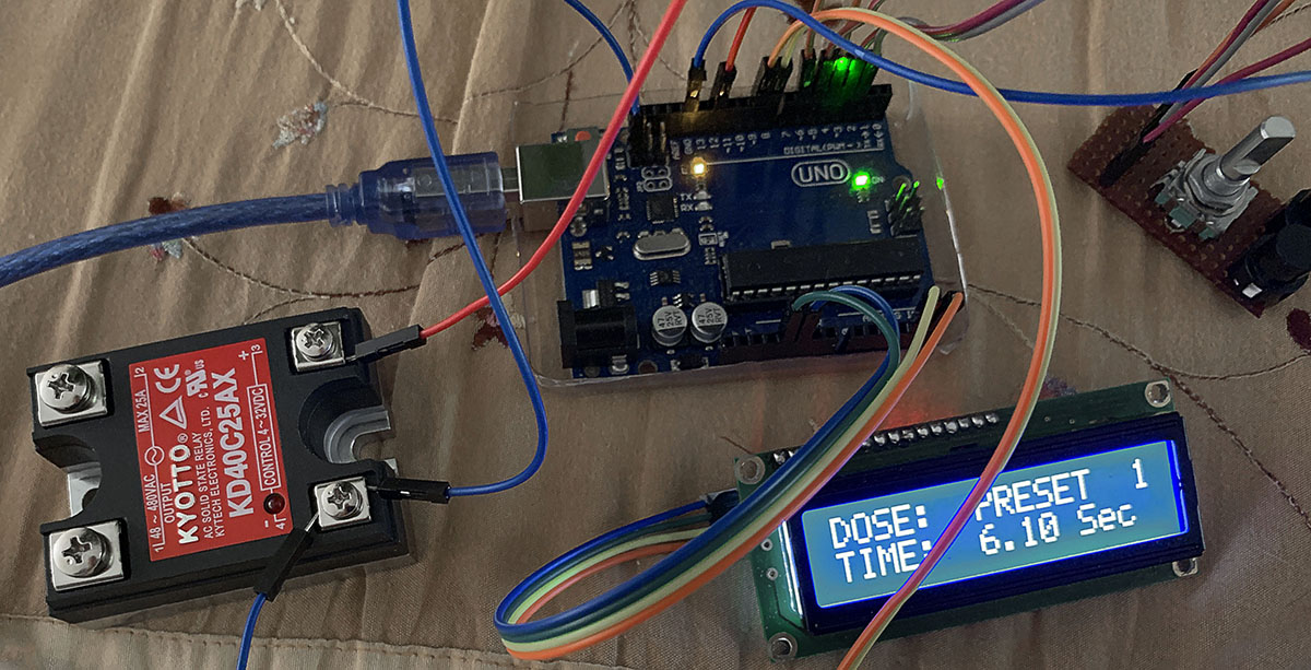
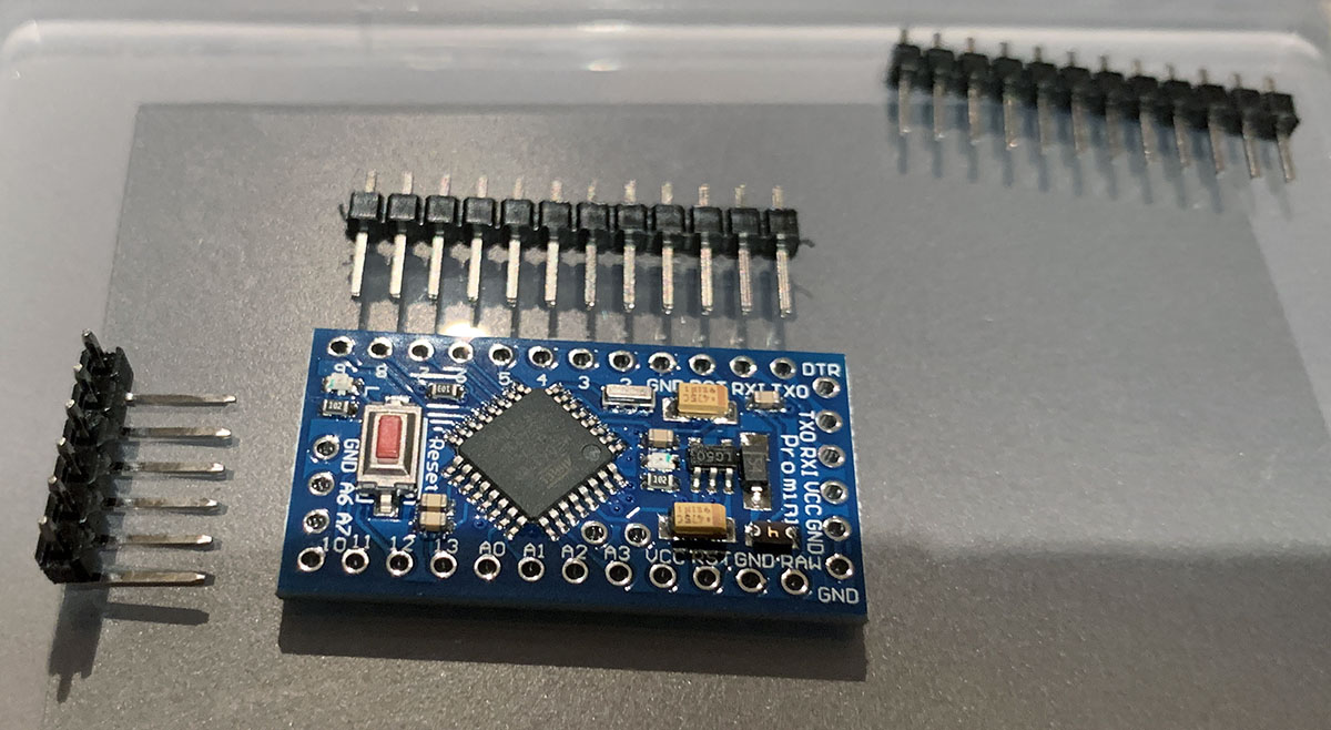
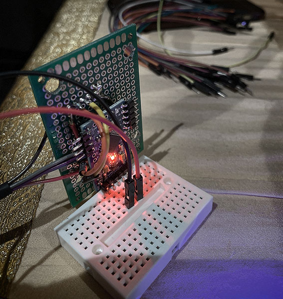


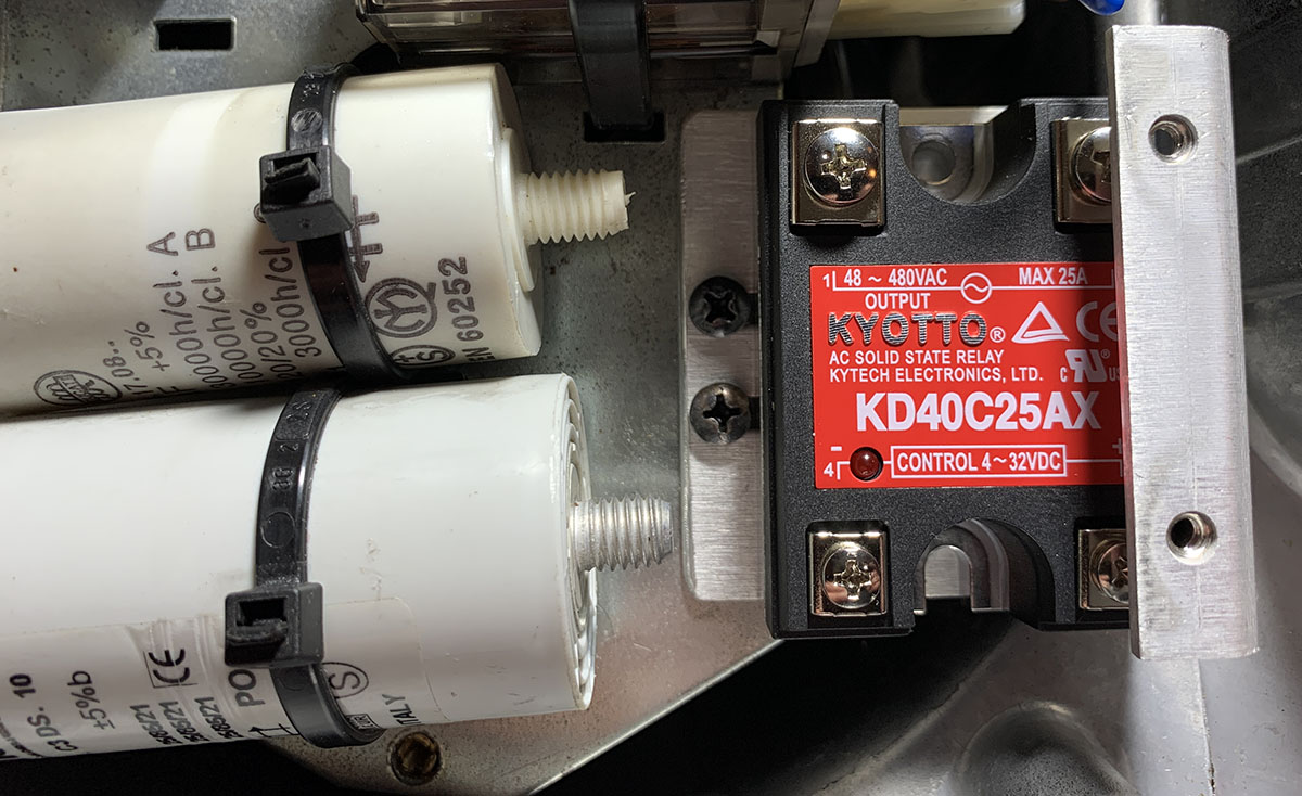
The timer module operates the grinder via a Solid-State Relay (SSR), a 480V DC-AC 25A zero-crossing high-end module is used. The original 16A mechanical relay was replaced with the SSR controlling the motor directly. The SSR was also mounted onto the main power module.
A small 5V power supply module is used and also mounted to the main power module for providing 5V supply rail for the timer module.
Final integration of the components, switches and control encoder neatly fitted into the existing case.

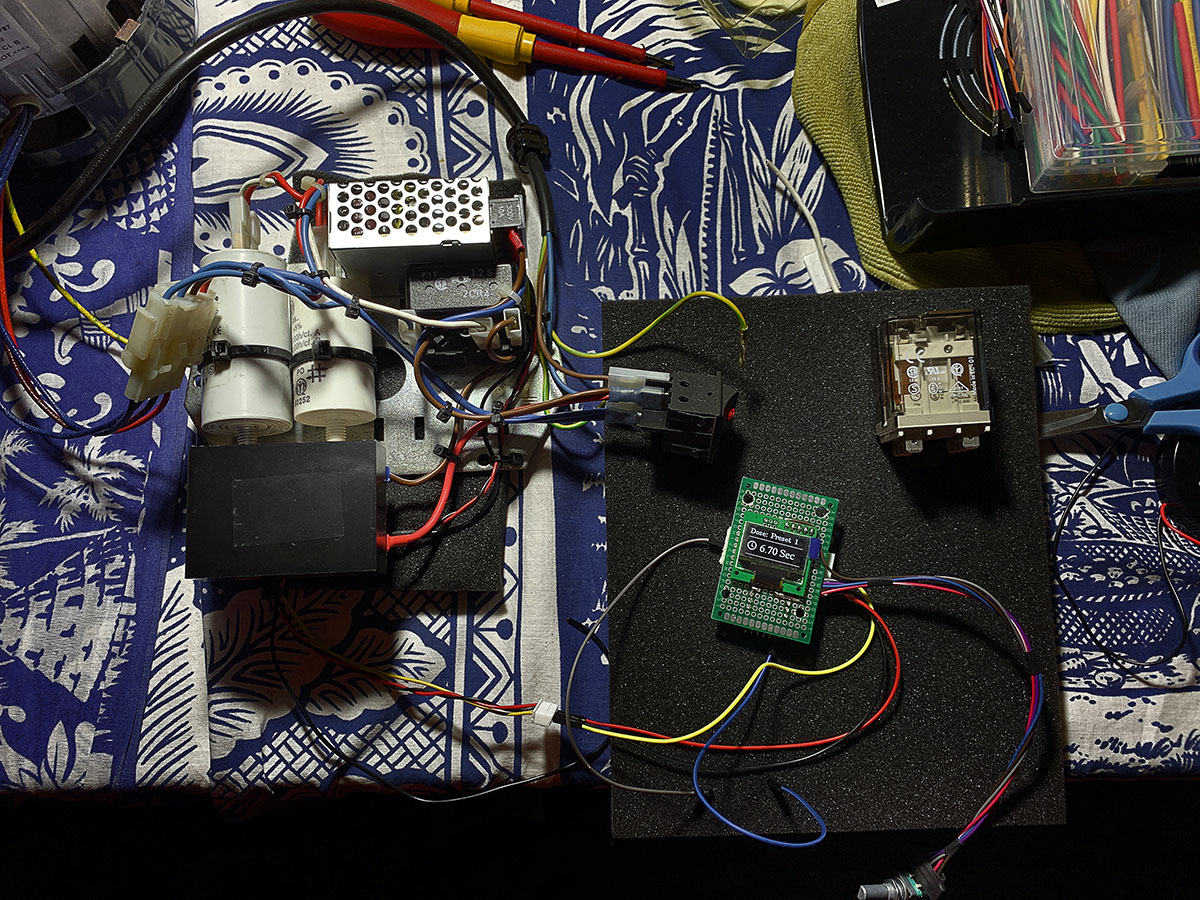
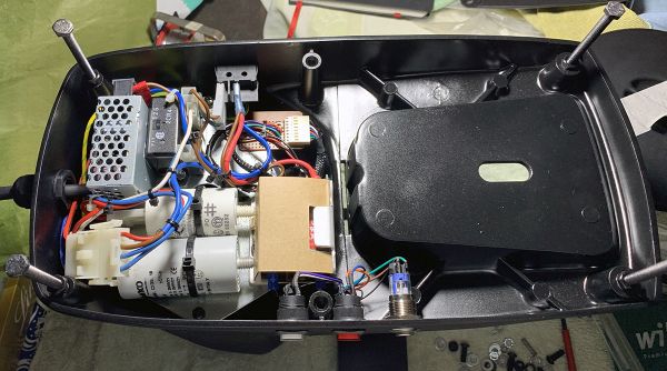
With the timer module completed and tested, the next step is to mark-out the cut-out and mounting holes for the screen and drill of the hole for the three control switches and encoder
The next phase of the project comprised of marking-up for the screen cut-out, drilling and tapping of holes for screws and switches.
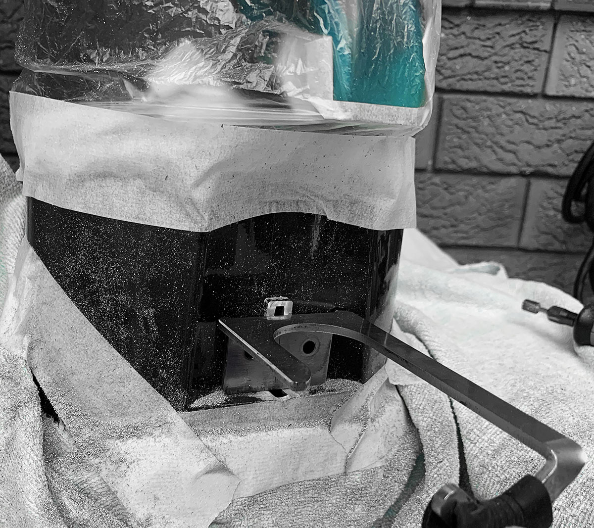
Some considerable time was spent to carefully and slowly cut out the screen hole to ensure a snug fit. The next step was to cut away the old support post that was used to hold the dosing chamber and allow the portafilter fork to sit in nicely.
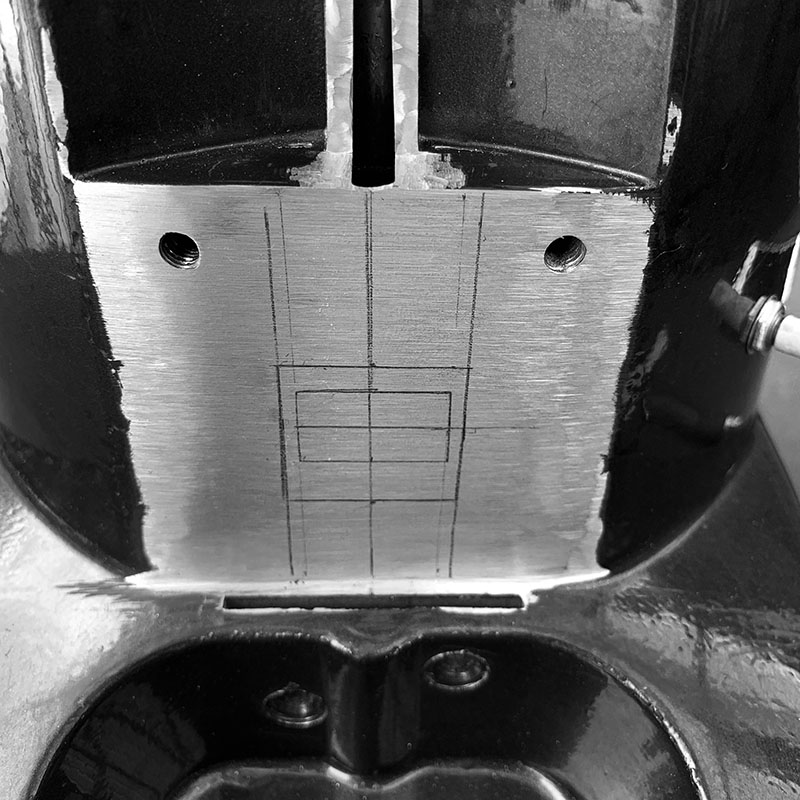
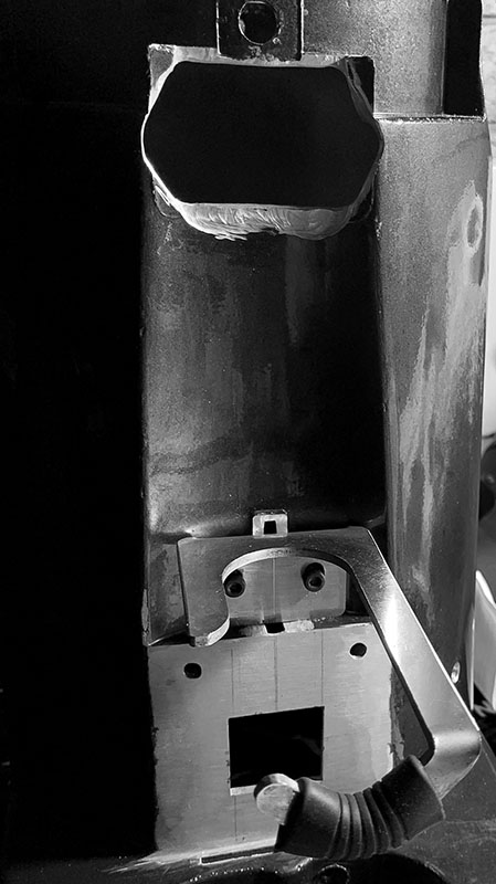



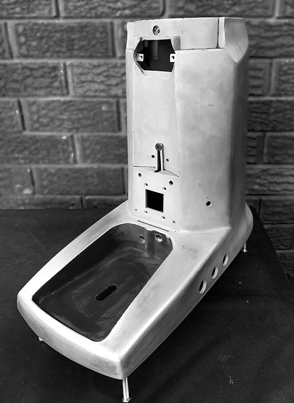
Once all the metalwork was completed, the next step was completing the aesthetic and cosmetic aspects, which itself was always on the design board.
First challenge was to engineer a solution to finish the front of the grinder. A plywood template was cut to shape, with initial thoughts to use timber as the front feature, however this changed in favour of an aluminium fascia.
Once final fitment tests had been completed, it was time to prepare the housing for painting, however first task, to sandblast the housing.
Monday 15 June 2020, the week commenced with a full day of sandblasting the housing and making it ready for priming on the next day.
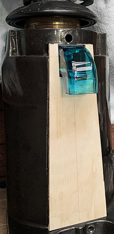

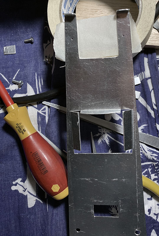
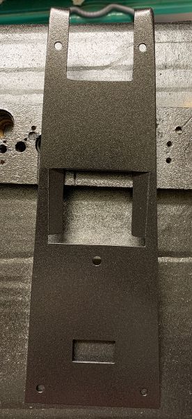
Among several engineering challenges (or rather more on final aesthetics), was ongoing brainstorming on solutions to complete the front fascia of the grinder and to resolve the original gap left from the dosing chamber cover at the top of the grinder.
The front fascia was first mocked up in card, then 3mm ply and eventually translated to 1.2mm aluminium. The aluminium stock was fully hand-cut (using a hand nibbling tool) and finished by hand. Final fitment test was completed prior to paining.
Above the portafilter holder, a space was built into the front face to allow for positioning of the filter under the spout, as a bonus can also aid in holding the filter.
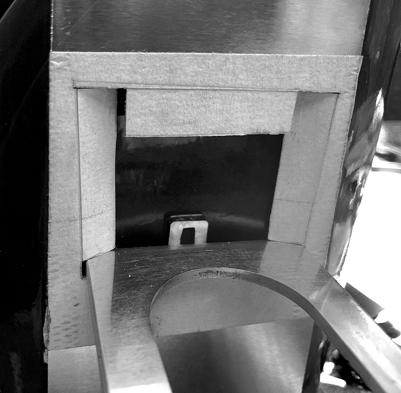
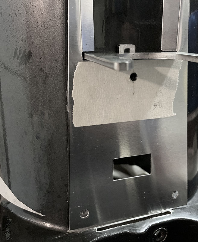
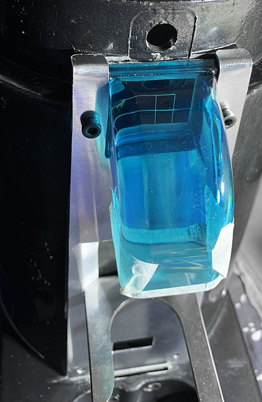
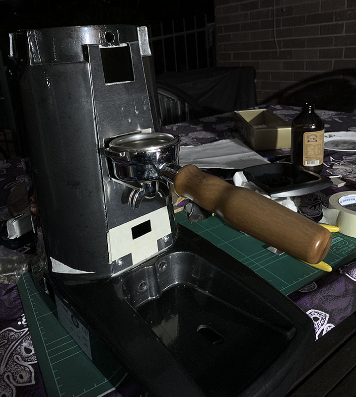
Throughout the project, a constant design thought was placed on how to fill-in and blend and the existing inset at the top of the grinder (which was where the lid of the dose chamber was mounted) in an aesthetically pleasing way.
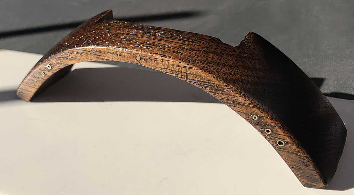
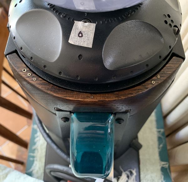
Eventually, Tasmanian Oak was used as the material of choice, Wood would add a "warm tone" feature to the project. Three sections of wood were cut and glued prior to sanding and contouring the piece.
Two Neodymium magnets are used to secure the piece to the body and allow for its removal if require disassembling the front to remove the spout for servicing purposes.

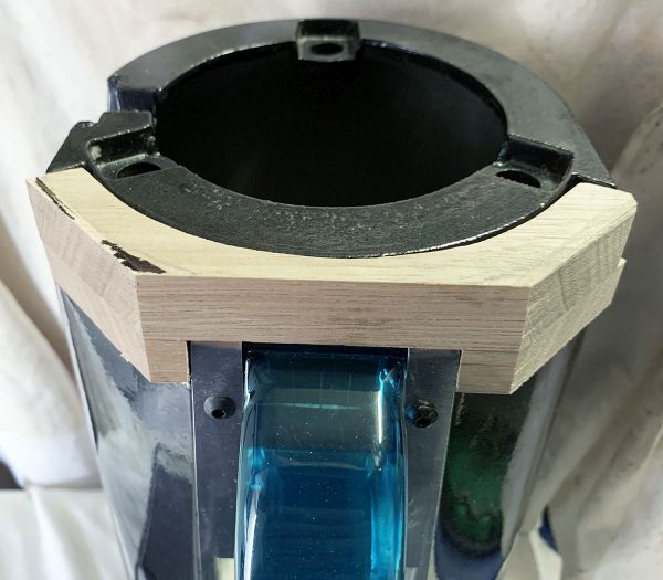
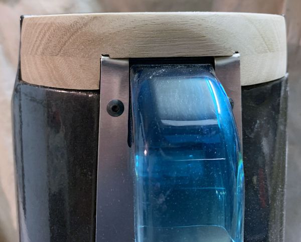
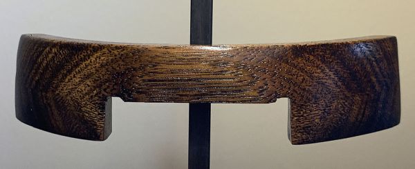
Following sanding and contouring, the wood trim was given several coats of walnut stain before two coats of Scandinavian Oil, and final coats of beeswax.
Painting commenced on 16 June 2020, The housing was given a coat of primer, followed by 5 coats of black satin paint. A final sand texture finish was achived through the spraying technique. Allowing the paint to cure, a final protective clear coat was applied to seal.
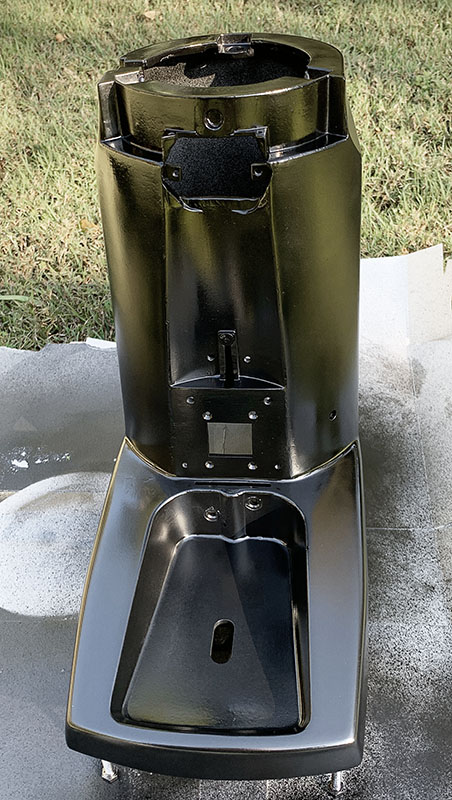
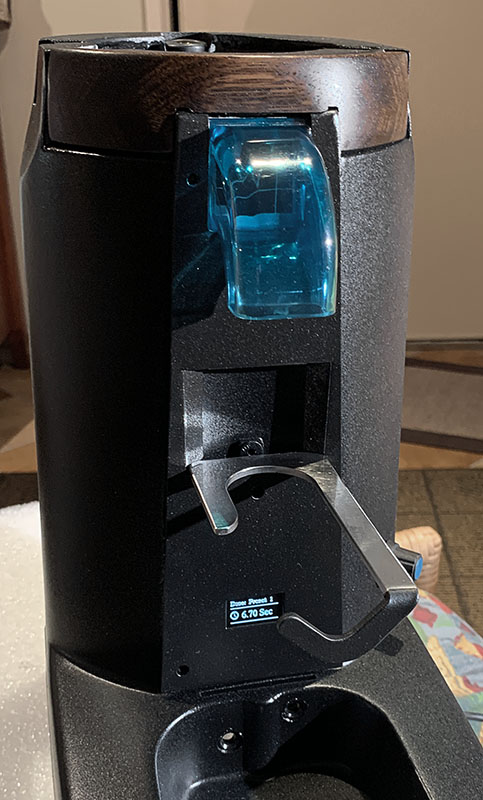

Additional work completed over several days, making up the wiring looms and performing final adjustments to the Electrical components. It was at this point, the decision made to remove the old 16A mechanical relay and control the grinder direct from the Solid-State Relay.
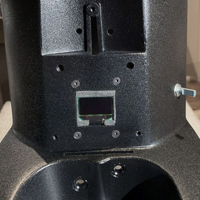
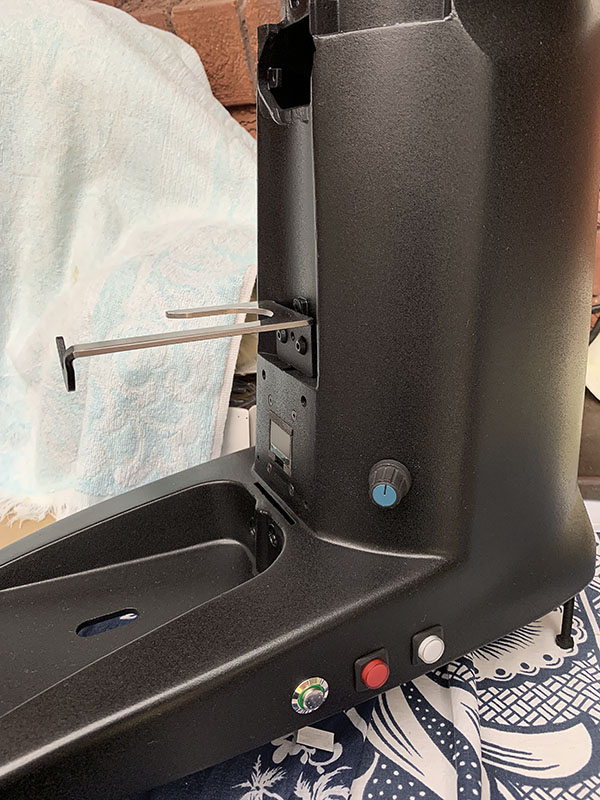
Assembly of the grinder was completed on 22 June 2020 with full tests, adjustment and calibration to follow. As part of the original reengineering, a Mazzer Anti-static screen was Initially installed on the spout, however during the initial test, it was found the flow of grinds was poor, and eventually the outlet chocked up.
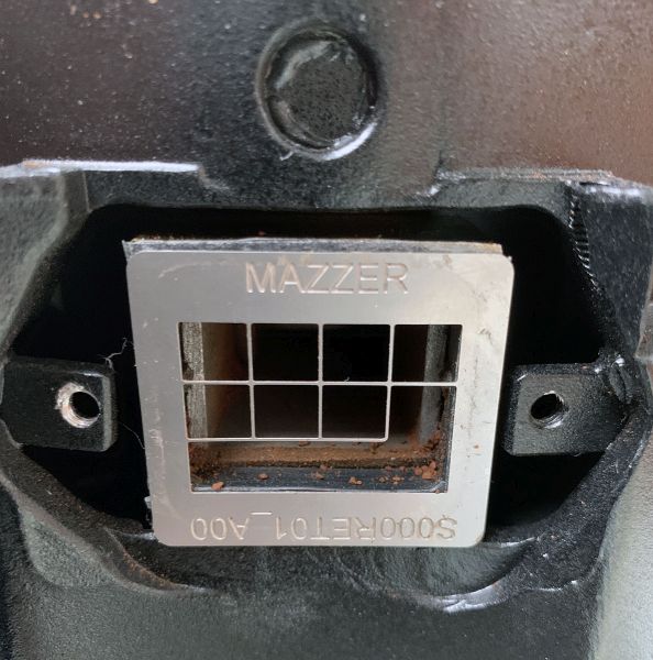
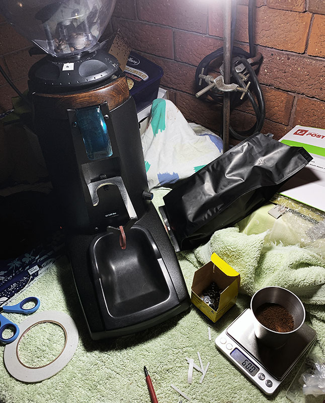

Following further discussion and brainstorming with Dean, some modifications was made to the screen by removing a segment and opening the screen a little further, this proved very successful with nice consistency in the dose.
Naturally, there is come coffee retention within the outlet, however this is expected considering the original design of the grinder outlet was to a dose chamber.
Following successful testing, the screen was position on the outlet port and foam tape used to form the final gasket.
Following the completion of the project, a final added detail to the wood trim was grind finesse and direction Indicators. A simple series of brass rod sections with different diameters where inserted into the top edge of the wood to provide a visual aid.
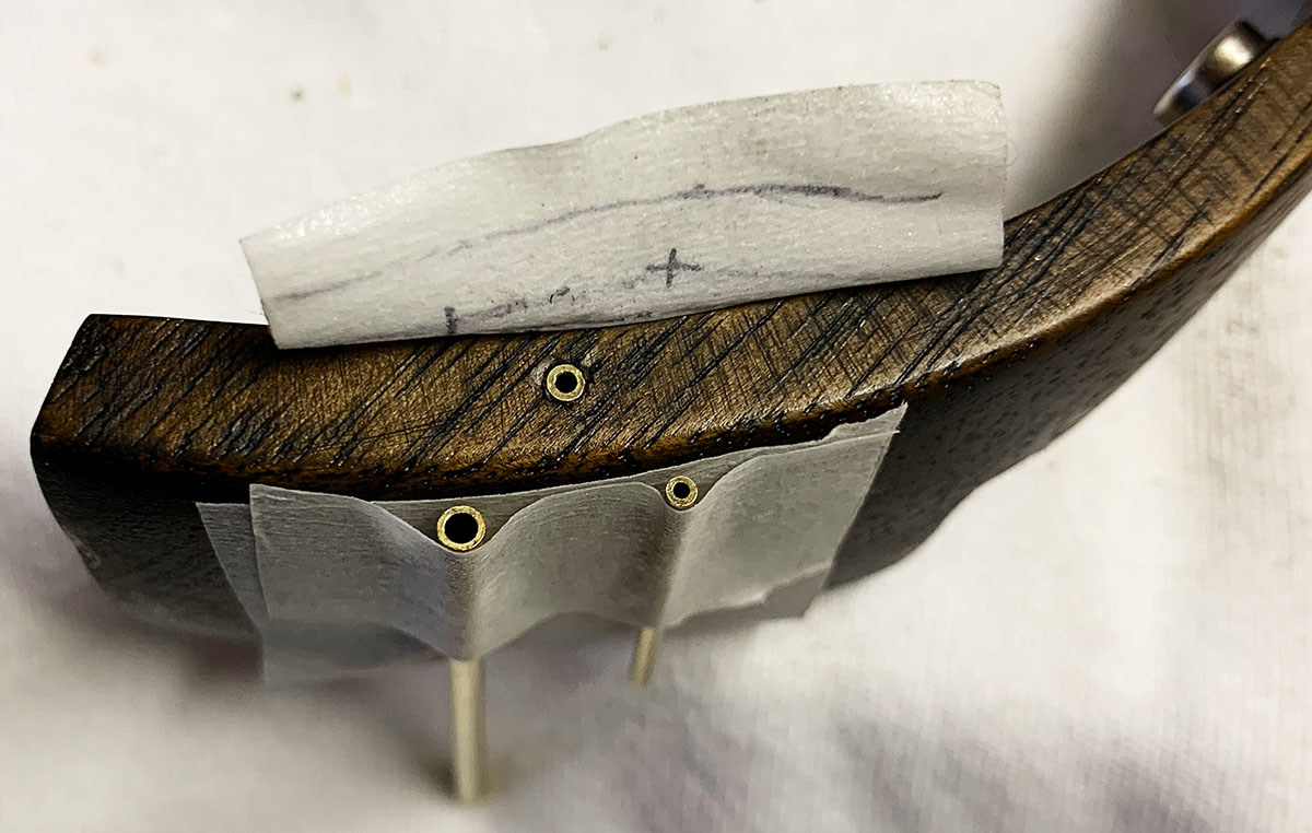
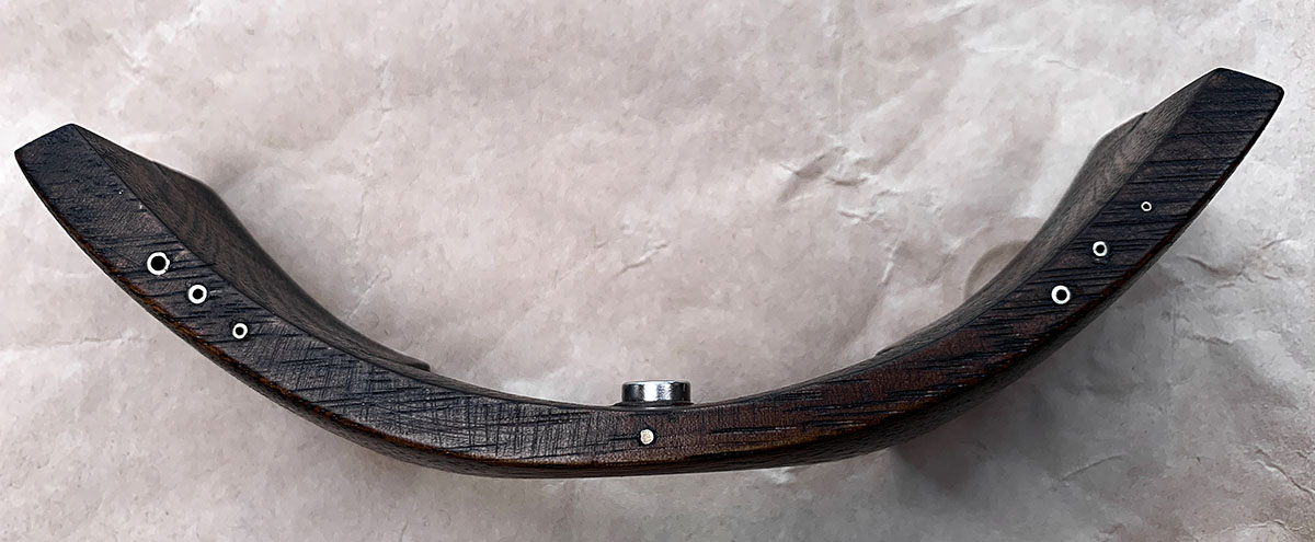
Following on close to 6 months work on the project, the final tests and calibration completed, the project was officially completed on 25 June 2020.
The Grinder together with my old ECM Giotto now has a new home at my sister and brother-in-law's home in the Hunter Valley.

Update
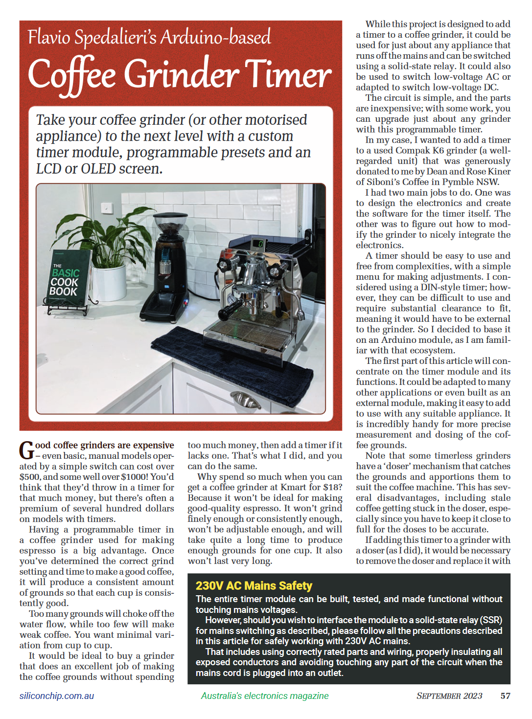
The significance of this project had it published in the September 2023 issue of Silicon Chip Magazine, an Australian Electronics publication.
A copy of the article can be purchased from Silicon Chip.
- Flavio Spedalieri -
Written: 10 November 2020
Updated: 30 September 2025
This Document Complies to W3C
XHTML 1.0 Strict Standards


